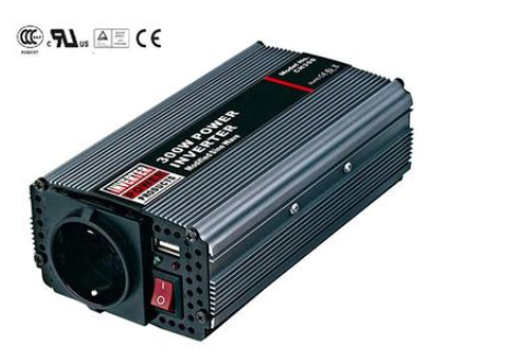
The DC to AC power inverter the dc energy (battery, storage battery) into alternating current (generally sinusoidal or square wave of 220v50HZ). Generally speaking, an DC to AC power inverter is a device that converts direct current (DC) into alternating current (AC). It consists of inverter bridge, control logic and filter circuit.
Simply put, an DC to AC power inverter is an electronic device that converts low-voltage (12 or 24 or 48 volts) direct current into 220 volts alternating current. The name comes from the fact that inverters are usually used to convert 220v ac to dc. In a "mobile" era, mobile office, mobile communications, mobile leisure and entertainment. In the mobile state, not only the low-voltage dc power supplied by batteries or batteries is needed, but also the 220v ac power which is indispensable in the daily environment, so the inverter can meet the demand.

According to the institute of electrical and electronic engineers (IEEE) for the spectrum of classifying tables, low frequency power inverter makes the frequency of 30 ~ 300 KHZ, intermediate frequency is 300 ~ 3000 KHZ, the frequency of high frequency power makes for 3 ~ 30 MHZ, frequency range in 30 ~ 300 MHZ for high frequency power makes, in 300 ~ 1000 MHZ uhf. Relative to the low frequency power inverter makes the signal, the signal of high frequency power inverter makes changes very fast, a mutation; The low-frequency signal changes slowly and the waveform is smooth.
The DC to AC power inverter of the power grid into a stable 12V dc output, while the inverter converts the 12V dc voltage output by Adapter into a high-frequency high-voltage alternating current. The two parts also use the pulse width modulation (PWM) technology. The core part is a PWM integrated controller, Adapter USES UC3842, inverter USES TL5001 chip. The operating voltage range of TL5001 is 3.6 ~ 40V, and it is equipped with an error amplifier, a regulator, oscillator, PWM generator with dead zone control, low-voltage protection circuit and short-circuit protection circuit, etc. Input interface: there are 3 signals in the input part: 12V dc input VIN, working enable voltage ENB and Panel current control signal DIM. The VIN is provided by Adapter, and the ENB voltage is provided by MCU on the motherboard. Its value is 0 or 3V. When ENB=0, the inverter does not work, while when ENB=3V, the inverter is in normal working state. DIM voltage is provided by the mainboard, and its variation range is between 0 and 5V. When different DIM values are fed back to the feedback terminal of PWM controller, the current provided by the inverter to the load will also be different. The smaller the DIM value is, the larger the current output by the inverter will be. Voltage starting circuit: ENB is at high voltage.
The inverter converts the dc energy (battery, storage battery) into alternating current (generally sinusoidal or square wave of 220v50HZ). Generally speaking, an inverter is a device that converts direct current (DC) into alternating current (AC). It consists of inverter bridge, control logic and filter circuit.