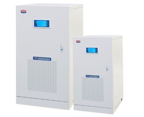
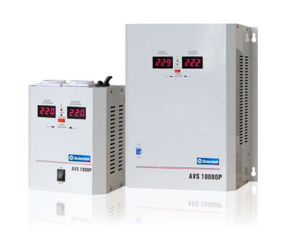
An AC voltage regulator is used in many applications where a constant and stable voltage is required. It is a device that regulates the voltage of a system so that it will remain within a certain range at all times.
A voltage regulator is most commonly found in appliances or equipment that require continuous current and voltage levels. It regulates the voltage by introducing an adjustable signal to a voltage supply. A common example is when an appliance or equipment needs a certain voltage to operate, such as a refrigerator.
The first part of the voltage regulation process is the series factor. It regulates the volume of power in a series circuit by introducing an adjustable signal that controls the voltage in series. In a single-phase power supply, there is only one signal source(DC switching Power Supply: Adjustable Switch-Mode Power Supply). In the case of a three-phase power supply, there are three signal sources that regulate the output voltage from the power supply.
The second part of the automatic voltage regulator involves the demand filter. This device removes power from a circuit that exceeds a set amount. It is applied to the output of the regulator.

In addition to regulating the output, the demand filter also has an effect on the energy consumption of the power supply. It effectively turns the power supply off if it has no power left to provide. It also has a negative effect on energy production because it is actually connected to the power supply.
The third step of the voltage regulator is the electronic power filter. This is simply the last step before the whole device is turned off. It is very important because it prevents some of the harmful effects of the voltage regulator.
The filtering system removes power from the power supply that has an effect on the energy production of the power supply. It is a method of reducing the amount of energy consumed by the power supply.
The electronic voltage regulator consists of three components: the voltage regulator, the power filter, and the demand filter. These three components are designed to effectively control the voltage and energy consumption of the power supply. They can be placed together or separated to the desired location.
For instance, if you place the voltage regulator above the electronic voltage regulator, the electronic regulator will be able to regulate the voltage of the power supply through the electronic voltage regulator. However, if you place the voltage regulator on the bottom side of the electronic voltage regulator, the electronic voltage regulator will have to regulate the energy output. The power filter will not be able to do its job properly since the energy produced would exceed the power required.
The automatic voltage regulator is the ultimate energy-efficient device. With it, you can avoid having problems such as making the electric company pay for excessive power consumption, which will add up to your electric bill.
The electronic voltage regulator allows you to maintain your electricity consumption level, especially in emergency situations where you may be short of electricity. Thus, you can be sure that the voltage you are using is at the right level, especially when you need to switch off your power source to prevent damage to your equipment.
With the installation of the voltage regulator, you can still save on electricity costs even though you have an alarm. You can also put it in place in several rooms of your house and you can still use the money you saved on electricity to improve the quality of your home.
A digital voltage stabilizer is used in most home entertainment equipment for digital signal generation. This device can also be used to stabilize the voltage output of an audio amplifier or other electronic devices.

Wall Mount Relay type Automatic Voltage Regulator AVR-WG Series
The analog components of a digital voltage stabilizer are first grounded and then placed in a small box to protect them from any contact with the outside world. It has become increasingly common for digital devices that generate digital signals to have a digital voltage stabilizer. An automatic voltage regulator (AVR) is an example of this type of device.
This type of circuit is designed to prevent damage to the analog component of the device. There are two main types of resistors used in an AVR. The first type is used to reduce the input level to the device. The second type is used to limit the maximum output level of the device.
The digital stabilizer can be divided into two main categories: analog to digital converters and digital to analog converters. In both cases, the actual electronics are the same.
The most basic type of voltage stabilizer is the one that simply uses a resistor and an amplifier to turn the output of the analog component of the device into the signal that it is used to amplify. The resistor can be extremely low value or very high value.
In some cases, the resistor can be a cheap and simple design such as an attenuator but in many cases, the resistor must be designed with a control function in mind. The simplest form of a resistor is a capacitor which stores charge on to itself when a current is applied to it.
A capacitor can be used to provide a small amount of filtering of noise in a very small plastic box. The capacitor can be used as a voltage stabilizer or be used as a simple resistor.
A type of resistor that is known as a low pass filter can be used to reduce the impact of a digital signal. It can be used to control noise and then used as a stabilizer. This type of resistor is referred to as a low-pass filter.
A low-pass filter can be used to dampen a digital signal or it can be used to amplify the digital signal before it passes through the low-pass filter. The difference between a digital voltage stabilizer and a low-pass filter is that a low-pass filter can amplify the signal much more than a digital voltage stabilizer can. This is called the bandwidth of the signal.
A resistor that has a much larger bandwidth than a resistor can be used as a low-pass filter. However, when choosing a resistor to use as a low-pass filter, the resistor must be selected for its impedance. Higher impedance will require less current to pass through the resistor for it to be a good low-pass filter.
If the low-pass filter is in effect at a very high frequency, the amount of noise produced by the device may exceed the threshold of the resistor being used as a low-pass filter. This can cause distortion and may even overload the output of the device. Some electronic devices have low pass filters at frequencies as high as 100 kHz or even higher.
When the digital voltage stabilizer is designed for use with a digital audio amplifier, the two types of resistors mentioned above should be used. The actual resistance in a digital audio amplifier is a much simpler circuit that does not have a low-pass filter and does not have a bandwidth of a very high frequency. The circuit design must incorporate a high-frequency stability rating in order to achieve the best results possible from a digital voltage stabilizer.